New optoelectronic devices for the Near and Mid-Infrared spectral range open completely new possibilities for portable sensors creation. Using infrared LED-PD optopairs allows developing an instrument that is smaller, less expensive and energy-saving.

How to Start
Introduction
Let's find out how to deal with LMSNT LEDs and photodiodes on the example of methane concentration measurement. Methane has a strong absorption band at 3.4 μm, so we need an optical system that will be sensitive in this region. We will consider setting up a 1-channel measurement scheme.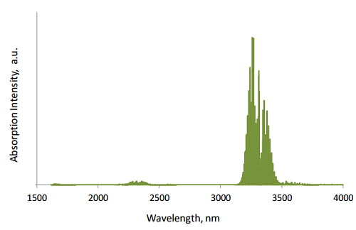
Methane absorption spectrum
1. light-emitting diode (LED)
2. LED driving device
3. photodiode (PD)
4. PD signal processing device
5. synchronisation device between LED and PD
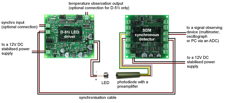
Common system scheme
1. Light-emitting diode (LED)
The name of every our LED corresponds to its emission spectrum. The needed LED with peak wavelength at 3.4 μm has the name Lms34LED:
Lms34LED emission spectrum at 150 mA qCW.
2. LED driving device
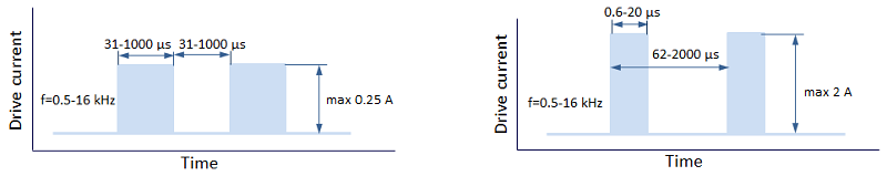
A device to drive an LED can be either a signal generator or LED Microsensor NT driver designed specially for our LEDs. We propose 4 types of LED drivers:Here is the principle of signal generating:

To drive LEDs in optimal way we recommend using Quasi Continuous Wave (qCW) mode with duty cycle 50% or 25% to obtain maximum average optical power and short Pulse modes to obtain maximum peak power. Hard CW (continius wave) mode is NOT recommended.
More about operation modes:
3. Photodiodes
The name of every our PD corresponds to its cut-off wavelength of photosensitivity and sensitive area. For methane measurement we need a photodiode spectrally-matched to the Lms34LED. These are Lms36PD series photodiodes with sensitivity cut-off about 3.6 μm with sensitive area size 0.5 mm – Lms36PD-05 and 0.3 mm – Lms36PD-03 and Lms36PD-03ws. Here is the spectrum of Lms36PD-05:
Lms36PD-05 photosensitivity spectrum.
Photodiode is an electronic device which converts light into either current or voltage, depending on the mode of operation. Typical photodiode connection schemes are presented below.
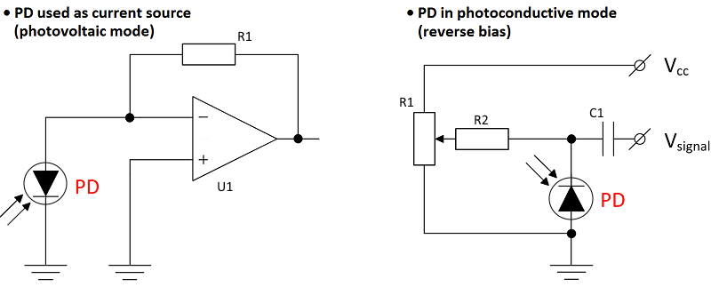
Schemes are presented for general understanding only. Polarity and connection schemes for the exact photodiode models are presented in the appropriate technical passports.
For best performance, we recommend using photodiode as current source (photovoltaic mode).
It is strongly recommended to screen the photodiode and connect the ground pin of the photodiode to the common ground of the used circuitry.
4. Photodiode preamplifier
You may choose photodiode with already built-in preamplifier – LmsXXPD-XX-R(W)-PA type – or a standalone preamplifier board – PAb. Microsensor NT PA preamplifier works with photodiode in photovoltaic mode, converts the obtained current into voltage and amplifies it.More about photodiodes with preamplifier:
5. Synchronisation device between LED and PD
For obtaining higher signal-to-noise ratio with LED-PD optopairs it is recommended to apply synchronous detection. In this case photodiode detects signal from an LED only when the driving pulse is applied, and conversion of the obtained pulsed signal to the direct signal with additional amplification is performed. For these purposes we propose LMSNT SDM synchronous detector, which synchronises LED with a driver and photodiode with a built-in preamplifier operation, measures the voltage signal from the output of photodiode preamplifier and converts it to the DC voltage signal proportional to amplitude of voltage from input with amplification.More about SDM synchronous detector:
Connections and setup
Having the abovementioned devices you may proceed to the connections.If you use a photodiode with a standalone version of a preamplifier, start from step 1.
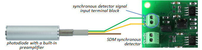
If you use a photodiode with a bulit-in preamplifer, start from step 4.
1) Connect a PD to the PD preamplifier (soldering is needed by default).
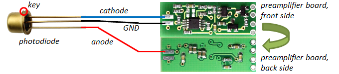
- Please observe the PD polarity: PD anode is marked with a RED dot, PD cathode – with a BLACK dot.
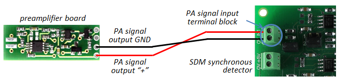
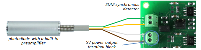
2) Connect the preamplifier output with an input of SDM synchronous detector.
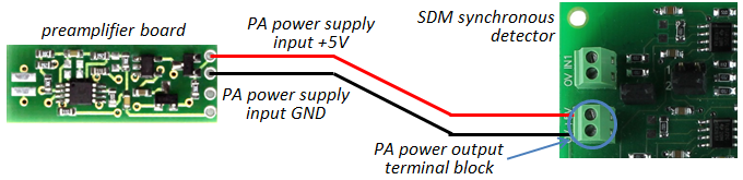
3) Connect a 5V power output of the SDM synchronous detector to the preamplifier power input, proceed to step 6.
- Please check your connection circuit before turning the PD on.
- Please do not connect the PD to the multimeter.
4) Connect the preamplifier output with an input of SDM synchronous detector.
5) Connect a 5V power output of the SDM synchronous detector to the preamplifier power input.
6) Select the needed signal gain and averaging time on the SDM synchronous detector.
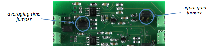
You can find out more about adjustment of the signal gain and averaging time in the appropriate SDM synchronous detector manual.
7) Connect the LED pins to the LED connection terminal block of the LED driver.
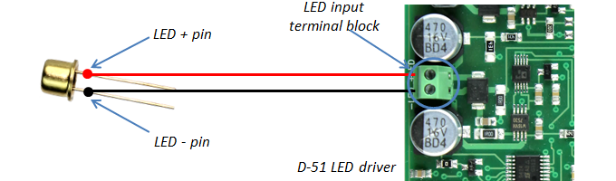
- The pin with red dot must be connected to the “+” sign of the driver terminal block.
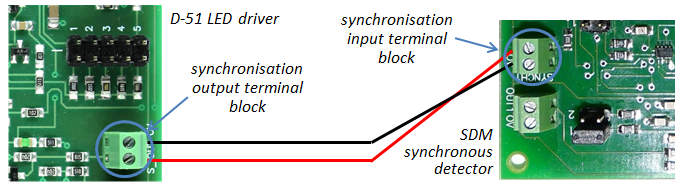
8) Connect the synchronisation output of the LED driver with the synchronisation input of the synchronous detector via synchronisation cable.
9) Select the needed mode of the LED driver (cuurent amplitude, frequency, pulse duration) if you use a driver model with adjustable parameters.
You can find out more about driver modes and their adjustment in the appropriate Driver Instruction Manual.
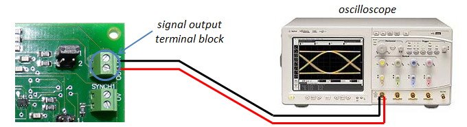
10) Connect signal output terminal block of the SDM synchronous detector with signal observing device (multimeter, oscillograph or PC via ADC).
11) Connect a 12V DC stabilized power supply to the LED driver and SDM synchronous detector (red wire to the “+”; black wire to the “‒”).
After taking the steps above you will see the signal value on your signal observing device.